


AMWEI Thermistors Sensor manufacture PTC & NTC thermistors (THERMally sensitive resistors) and thermistor temperature sensors probe. PTC thermistors application cover overcurrent overload and short circuit protection , telecom protection, temperature sensing protection, motor sensing protection,motor starting, lighting soft switching time delay, self-regulation constant heating, linear silicon PTC thermistor temperature sensor, etc. NTC thermistors application cover power thermistor for inrush current limiting surge suppressing, NTC thermistor for temperature measurement, indicator, temperature compensation, temperature control, in either radial leaded, axial leaded, or customer tailored thermistor temperature sensor probe assembly, for surface temperature sensing or liquid immersion temperature measurement.


AMWEI Featured Thermistors Products
Industry Application
AMWEI Thermistors Sensor Application can be found in motor, transformer, power supply meter & instrumentation, home appliance, telecom & network, HVAC & R,home electric appliance, white goods, food service, consumer electronics, lighting, office automation equipment, consumer electronics, data logger, industrial process control, medical, automotive, etc.


Thermistors Selection
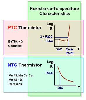
PTC NTC Thermistor Characteristics
-
- What is PTC Thermistors?
What difference between Positive and Negative Temperature Thermistors? - 3 PTC Thermistors characteristics, Resistance vs. Temperature RT Characteristic, Voltage vs. Current VI characteristic, Current vs Time Characteristic.
- PTC Thermistors Application Cautions for Soldering, Mounting, Cleaning.
- How NTC Thermistor beta value is calculated?
- How to select PTC Thermistors for current protection?
- What Advantage of using PTC Thermistors as heating elements?
- Why NTC Thermistor is popular for temperature measurement? How to Select?
- How to Select Packaged Thermistor Temperature Sensor Probe Assembly ? 6 Steps
- How to Select AMWEI PTC Screw Clamp Type to Cross Murata PTFM Overheat Temperature Sensor in Lug Terminal ?
- What is PTC Thermistors?
Find by Category
Axial Lead Glass Sealed NTC Thermistor Products, Radial Lead Epoxy Coated NTC Thermistors Products, NTC Thermistors ICLs Inrush Current Limiter, Radial Glass Bead NTC Products, Murata PTFM Series PTC Overheat Sensing Lug Screw Clamp Cross Products, Murata PTGL Series POSISTOR 250/265V PTC Thermistor Overcurrent Protection Cross, Overcurrent Protection TDK Epcos B598** C830-C890 PTC Leaded Coated 230V, Self-regulating PTC thermistors Heating Elements, Thermometrics YQD 265V 120C PTC Current Protect Radial Wire Resin Coated, More…
Tag Cloud
Silicon Temperature Sensors NXP KTY8X Cross Products(13), ICLs Inrush Current Limit NTC Thermistors 1 Ohm Products (8), ICLs Inrush Current Limit NTC Thermistors 5 Ohm Products (7), ICLs Inrush Current Limit NTC Thermistors 10 Ohm Products(9), Kilowatt-hour Meter Overload PTC Protection(16), Measuring Instrument Overload Short Circuit Protection PTC Products (9), NTC Thermistor Temp Sensor 2K Ohm Product(5), NTC Thermistor Temp Sensor 10K Ohm Product (7), NTC Thermistor Temp Sensor 50K Ohm Product(5), NTC Thermistor Temp Sensor 100K Ohm Product (7), TDK S153 Series ICLs Inrush Current Limit NTC Thermistors Cross (7), Transformer Overload Protection PTC (31), Outside Transformer Windings Coil PTC thermistor(25), PTC Heater Chips (9), More…
PTC Thermistors Characteristics Glossary
PTC Thermistors Application Cautions
PTC Thermistors Manufacturing Process & Quality Control
NTC Thermistors Characteristics Glossary
NTC Thermistors Manufacturing Process & Quality Control
NTC Sensor Selection Reference
How to Select NTC thermistor for Inrush Current Limiting
Charging Control with AMWEI NTC thermistor
Reliable limiting of current surges by AMWEI NTC and PTC thermistor
Thermistors Catalog
PTC Heater Chips Disks Honeycomb
Soldered Coated Insulated Metal Conductive Heaters
PTC Liquid Heater Cartridge Flow through Build-in
PTC Convection Heaters Air Heater
PTC Diesel Fuel Heater
M8 Threaded Al Case 12V 160C PTC Cartridge Heater Assembly
PTC Heater 220V 110V 180C Polyimide Kapton Insulated 24x15x3.2mm
Surface Heater 110V 220V 260C AL Housing Flanged With Mounting Holes
Ring Heater 220V 110C D14.5/4.3mm
Inrush Current Limit NTC Thermistor
Radial Leaded Resin Coated NTC Thermistors Temperature Sensors
Axial Leaded Glass Encapsulated NTC Thermistors Temperature Sensors
Radial Glass NTC Thermistors
NTC Thermistor Temperature Probe
Ring Lug NTC Thermistors Temp Sensor 100KΩ β3950K 200C
Copper Tube NTC temp sensor
Flanged Stainless Steel NTC Sensor
Threaded Stainless Steel NTC Sensor
Food Cooker Meat Probe
Hex Head Screw Threaded Water Heater Boilers 50K 3950K Sensor
M6 Threaded Nickel Copper NTC 10K 3950K Probe Assembly
Clip-on Φ14mm Pipe Sensor 10KΩ