Power NTC Thermistors for Inrush Current Limiting Surge Suppression
Inrush Current Limit NTC Thermistor
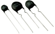
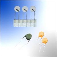
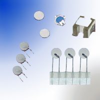
Inrush Current Limiting (ICL) Surge Suppression Power NTC Thermistor is polycrystalline mixed oxide ceramics made semiconductor type NTC Thermistor disc soldered with radial metal wire, coated with epoxy resin, function as a power resistor to limit the inrush current surge current in the turn-on stage.
Power NTC thermistor can be a cost effective device to limit the amount of inrush current in a switching power supply or other devices when the power is first turned on.
Power NTC thermistor limits surge current by functioning as a power resistor which drops from a high cold resistance to a low hot resistance when heated by the current flowing through it.
Inrush-current limiters power NTC thermistor protect circuits from undesirably high currents, suppressing high inrush current surges, while its resistance remains negligible low during continuous operation. Thanks to their low resistance in the operating state, Power NTC thermistor have a considerably lower power dissipation than the fixed resistors frequently used for this application.
In the cold state, i.e. at room temperature, the high initial resistance of the inrush current limiter effectively absorbs the power of peak inrush currents. As a result of the current load and subsequent heating, the resistance of the inrush current limiter then drops by a factor >30 – 50 to a few percent of its value at room temperature. The power consumption of the inrush current limiters is thus negligible in continuous operation – an outstanding advantage of NTC thermistor over fixed resistors.
Resuming operation after cooling down
After a load has been switched off, the NTC thermistor must be allowed to cool down to room temperature if its capacity for inrush current limiting is to be fully used. This can take from 30 seconds to two minutes depending on the disk size. In the case of switched mode power supplies, these cooling times are often a minor consideration because electrolytic capacitors in the circuit usually take longer to discharge fully. The NTC thermistor will therefore be cool enough to resume operation in the event of another short-term turn-on.
limiting surge current, suitable for the protection of switch mode power supply, UPS power, transformers, motors, various electric heating utensil, energy saving lights, ballast, various power circuit, amplifiers, colored displayer, monitors, color TV, filament protection, etc.
Power NTC thermistor components can also be used for the soft starting of motors, for example in vacuum cleaners with continuous currents of up to 20 A.
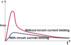
Comparison curve With Without Inrush Current Limiting Power NTC thermistor
·Low cost solid state device for inrush current suppression.
·Minimize line current distortion and radio noise.
·Protect switches, rectifier diodes and smoothing capacitors against premature failures.
·Prevent fuse from blowing in error.
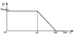
Power NTC Thermistor Load Temperature Characteristics
·Resin coated disk NTC thermistor with uninsulated lead-wires.
·Suitable for both AC and DC circuits up to a voltage of 265 V(rms).
·Wide range of resistance, current and dimension.
·Excellent mechanical strength.
·Suitable for PCB mounting.
NTC thermistors in a protective circuit mounting positions

NTC Thermistor for diode protection
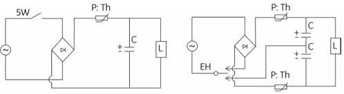
Power thermistor application circuits
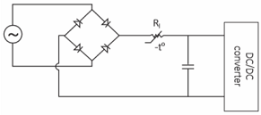
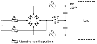
Typical Power Supply Circuit
The problem of current surges in switch-mode power supplies is caused by the large filter capacitors used to smooth the ripple in the rectified 60 Hz current prior to being chopped at a high frequency. The diagram above illustrates a circuit commonly used in switching power supplies.
In the circuit above the maximum current at turn-on is the peak line voltage divided by the value of R; for 120 V, it is approximately 120 x √2/RI. Ideally, during turn-on RI should be very large, and after the supply is operating, should be reduced to zero. The NTC thermistor is ideally suited for this application. It limits surge current by functioning as a power resistor which drops from a high cold resistance to a low hot resistance when heated by the current flowing through it. Some of the factors to consider when designing NTC thermistor as an inrush current limiter are:
- Maximum permissible surge current at turn-on
- Matching the NTC thermistor to the size of the filter capacitors
- Maximum value of steady state current
- Maximum ambient temperature
- Expected life of the power supply
Maximum Surge Current
The main purpose of limiting inrush current is to prevent components in series with the input to the DC/DC converter from being damaged. Typically, inrush protection prevents nuisance blowing of fuses or breakers as well as welding of switch contacts. Since most NTC thermistor materials are very nearly ohmic at any given temperature, the minimum no-load resistance of the NTC thermistoris calculated by dividing the peak input voltage by the maximum permissible surge current in the power supply (Vpeak/Imax surge).
Energy Surge at Turn-On
At the moment the circuit is energized, the filter caps in a switcher appear like a short circuit which, in a relatively short period of time, will store an amount of energy equal to 1/2CV2. All of the charge that the filter capacitors store must flow through the thermistor. The net effect of this large current surge is to increase the temperature of the thermistor very rapidly during the period the capacitors are charging. The amount of energy generated in the thermistor during this capacitor-charging period is dependent on the voltage waveform of the source charging the capacitors. However, a good approximation for the energy generated by the NTC thermistor during this period is 1/2CV2 (energy stored in the filter capacitor). The ability of the NTC thermistor to handle this energy surge is largely a function of the mass of the device. This logic can be seen in the energy balance equation for a thermistor being self-heated:
Input Energy = Energy Stored + Energy Dissipated
or in differential form: Pdt = HdT + δ(T – TA)dt
where:
- P = Power generated in the NTC thermistor
- t = Time
- H = Heat capacity of the NTC thermistor
- T = Temperature of the thermistor body
- δ = Dissipation constant
- TA = Ambient temperature
During the short time that the capacitors are charging (usually less than 0.1 second), very little energy is dissipated. Most of the input energy is stored as heat in the thermistor body. In the table of standard inrush limiters there is listed a recommended value of maximum capacitance at 120 V and 240 V. This rating is not intended to define the absolute capabilities of the thermistor; instead, it is an experimentally determined value beyond which there may be some reduction in the life of the inrush current limiter.
Maximum Steady-State Current
The maximum steady-state current rating of a thermistor is mainly determined by the acceptable life of the final products for which the thermistor becomes a component. In the steady-state condition, the energy balance in the differential equation already given reduces to the following heat balance formula:
Power = I2R = δ(T – TA)
As more current flows through the device, its steady-state operating temperature will increase and its resistance will decrease. The maximum current rating correlates to a maximum allowable temperature.
In the table of standard inrush current limiters is a list of values for resistance under load for each unit, as well as a recommended maximum steady-state current. These ratings are based upon standard PC board heat sinking, with no air flow, at an ambient temperature of 77° (25°C). However, most power supplies have some air flow, which further enhances the safety margin that is already built into the maximum current rating. To derate the maximum steady state current for operation at elevated ambient temperatures, use the following equation:
Iderated = Iderated = √(1.1425–0.0057 x TA) x Imax @ 77°F (25°C)
A few items of data are needed to scale an inrush current limiter NTC thermistor:
- Load capacitance of device to be protected (determination of minimum size of the component)
- Steady-state current and maximum ambient temperature
- Required reduction of inrush current
Load capacitance of device to be protected
The high inrush current of devices results from the higher energy required to turn on. In power supplies the energy requirement is primarily caused by load capacitors, in transformers by magnetizing energy. The associated turn-on operations load the inrush current limiter as a current pulse. So this energy must be known to select the right component. It can be converted into capacitance for a given voltage.
Steady-state current and maximum ambient temperature
Select the component so that the steady-state current does not exceed the maximum admissible current (Imax) of the inrush current limiter. The maximum admissible current is produced from the figure for Imax and the derating in 2.4 with the maximum ambient temperature.
When scaling a design, remember the possibility of line voltage fluctuations and different operating states (steady-state currents) of the device itself, and incorporate appropriate precautionary measures.
Required reduction of inrush current
Within this component model the maximum steady-state current then determines the highest possible cold resistance (R25) that can be used for an application.
The higher the cold resistance (R25) of the inrush current limiter, the more the inrush current is dampened. If the current limiting effect of a component is inadequate, choose a larger model.

| AMWEI Part No. | Resistance R25 (ohm) |
Max Stable Current (A) |
Approx. Resistance value @max current (Ω) |
Dissipation Factor (mW/oC) |
Thermal Time Constant (sec) |
Dimensions (mm) |
||
|---|---|---|---|---|---|---|---|---|
| Dmax | Tmax | F±1 | ||||||
| ICL09-3R4A | 3 ohm | 4A | 0.120 | 11 | 34 | 11 | 5.5 | 7.5 /5 |
| ICL09-5R3A | 5 ohm | 3A | 0.210 | 11 | 34 | 11 | 5.5 | 7.5 /5 |
| ICL09-8R2A | 8 ohm | 2A | 0.400 | 11 | 32 | 11 | 5.5 | 7.5/5 |
| ICL09-10R2A | 10 ohm | 2A | 0.458 | 11 | 32 | 11 | 5.5 | 7.5/5 |
| ICL09-16R1A | 16 ohm | 1A | 0.802 | 11 | 31 | 11 | 5.5 | 7.5/5 |
| ICL09-22R1A | 22 ohm | 1A | 0.950 | 11 | 30 | 11 | 5.5 | 7.5/5 |
| ICL09-33R1A | 33 ohm | 1A | 1.124 | 11 | 30 | 11 | 5.5 | 7.5/5 |
| ICL09-50R1A | 50 ohm | 1A | 1.252 | 11 | 30 | 11 | 5.5 | 7.5/5 |
| ICL09-80R0.8A | 80 ohm | 0.8A | 2.010 | 11 | 30 | 11 | 5.5 | 7.5/5 |
| ICL11-3R5A | 3 ohm | 5A | 0.100 | 13 | 43 | 13 | 5.5 | 7.5/5 |
| ICL11-5R4A | 5 ohm | 4A | 0.156 | 13 | 45 | 13 | 5.5 | 7.5/5 |
| ICL11-8R3A | 8 ohm | 3A | 0.255 | 14 | 47 | 13 | 5.5 | 7.5/5 |
| ICL11-10R3A | 10 ohm | 3A | 0.275 | 14 | 47 | 13 | 5.5 | 7.5/5 |
| ICL11-12R2A | 12 ohm | 2A | 0.462 | 14 | 48 | 13 | 5.5 | 7.5/5 |
| ICL11-16R2A | 16 ohm | 2A | 0.470 | 14 | 50 | 13 | 5.5 | 7.5/5 |
| ICL11-20R2A | 20 ohm | 2A | 0.512 | 15 | 52 | 13 | 5.5 | 7.5/5 |
| ICL11-22R2A | 22 ohm | 2A | 0.563 | 15 | 52 | 13 | 5.5 | 7.5/5 |
| ICL11-33R1.5A | 33 ohm | 1.5A | 0.734 | 15 | 52 | 13 | 5.5 | 7.5/5 |
| ICL11-50R1.5A | 50 ohm | 1.5A | 1.021 | 15 | 52 | 13 | 5.5 | 7.5/5 |
| ICL11-60R1.5A | 60 ohm | 1.5A | 1.215 | 15 | 52 | 13 | 5.5 | 7.5/5 |
| ICL13-1.3R7A | 1.3 ohm | 7A | 0.062 | 13 | 60 | 15.5 | 6 | 7.5 |
| ICL13-3R6A | 3 ohm | 6A | 0.092 | 14 | 60 | 15.5 | 6 | 7.5 |
| ICL13-5R5A | 5 ohm | 5A | 0.125 | 15 | 68 | 15.5 | 6 | 7.5 |
| ICL13-10R4A | 10 ohm | 4A | 0.206 | 15 | 65 | 15.5 | 6 | 7.5 |
| ICL13-15R3A | 15 ohm | 3A | 0.335 | 16 | 60 | 15.5 | 6 | 7.5 |
| ICL13-30R2.5A | 30 ohm | 2.5A | 0.517 | 16 | 65 | 15.5 | 6 | 7.5 |
| ICL13-47R2A | 47 ohm | 2A | 0.810 | 17 | 65 | 15.5 | 6 | 7.5 |
| ICL15-1.3R8A | 1.3 ohm | 8A | 0.048 | 18 | 68 | 17.5 | 6 | 10/7.5 |
| ICL15-1.5R8A | 1.5 ohm | 8A | 0.052 | 18 | 69 | 17.5 | 6 | 10/7.5 |
| ICL15-3R7A | 3 ohm | 7A | 0.075 | 18 | 76 | 17.5 | 6 | 10/7.5 |
| ICL15-5R6A | 5 ohm | 6A | 0.112 | 20 | 76 | 17.5 | 6 | 10/7.5 |
| ICL15-8R5A | 8 ohm | 5A | 0.178 | 20 | 80 | 17.5 | 6 | 10/7.5 |
| ICL15-10R5A | 10 ohm | 5A | 0.180 | 20 | 80 | 17.5 | 6 | 10/7.5 |
| ICL15-15R4A | 15 ohm | 4A | 0.268 | 20 | 85 | 17.5 | 6 | 10/7.5 |
| ICL15-20R4A | 20 ohm | 4A | 0.288 | 20 | 85 | 17.5 | 6 | 10/7.5 |
| ICL15-30R3.5A | 30 ohm | 3.5A | 0.438 | 21 | 85 | 17.5 | 6 | 10/7.5 |
| ICL15-47R3A | 47 ohm | 3A | 0.680 | 21 | 86 | 17.5 | 6 | 10/7.5 |
| ICL20-0.7R11A | 0.7 ohm | 11A | 0.018 | 24 | 89 | 22.5 | 7 | 10/7.5 |
| ICL20-1.3R9A | 1.3 ohm | 9A | 0.037 | 24 | 88 | 22.5 | 7 | 10/7.5 |
| ICL20-3R8A | 3 ohm | 8A | 0.055 | 24 | 88 | 22.5 | 7 | 10/7.5 |
| ICL20-5R7A | 5 ohm | 7A | 0.087 | 24 | 87 | 22.5 | 7 | 10/7.5 |
| ICL20-8R6A | 8 ohm | 6A | 0.142 | 25 | 105 | 22.5 | 7 | 10/7.5 |
| ICL20-10R6A | 10 ohm | 6A | 0.162 | 25 | 102 | 22.5 | 7 | 10/7.5 |
| AMWEI Part | Resistance R25 (ohm) |
Max Stable Current(A) | Approx. Resistance Value at Maximum Current (Ω) | Max Rated Power Pmax.(W) | Dissipation Factor (mW/oC) | Thermal Time Constant (s) | Dimensions (mm) | |
|---|---|---|---|---|---|---|---|---|
| Dmax | Tmax | |||||||
| ICL73T15-2.5R9.5A | 2.5 ohm | 9.5A | 0.044 | 5W | 22 min | 75 max | 17.5 | 6 |
| ICL73T15-5R8A | 5 ohm | 8A | 0.058 | 5W | 22 min | 75 max | 17.5 | 6 |
| ICL73T15-10R7A | 10 ohm | 7A | 0.098 | 5W | 22 min | 75 max | 17.5 | 6 |
| ICL73T20-1R16A | 1 ohm | 16A | 0.027 | 7W | 28 min | 110 max | 22.5 | 7 |
| ICL73T20-5R12A | 5 ohm | 12A | 0.047 | 7W | 28 min | 110 max | 22.5 | 7 |
| ICL73T20-10R8A | 10 ohm | 8A | 0.085 | 7W | 28 min | 110 max | 22.5 | 7 |
| ICL73T25-1R20A | 1 ohm | 20A | 0.021 | 9W | 30 min | 130 max | 29 | 8 |
| ICL73T25-5R14A | 5 ohm | 14A | 0.047 | 9W | 30 min | 130 max | 29 | 8 |
| ICL73T25-10R10A | 10 ohm | 10A | 0.084 | 9W | 30 min | 130 max | 29 | 8 |
| ICL73T30-1R30A | 1 ohm | 30A | 0.014 | 13W | 40 min | 190 max | 35 | 10 |
| ICL73T30-10R13A | 10 ohm | 13A | 0.056 | 13W | 40 min | 190 max | 35 | 10 |
| Test Item | Standard | Test Conditions | Specifications |
|---|---|---|---|
| Lead wire tensile | IEC 60068-2-21 | Test Ua: Force 20N, On 10 Seconds; |
ΔR25/R25 <15%, No visible damage |
| Solderability | IEC 60068-2-20 | 245 ±3℃, 3 ± 0.3 sec | At least 95% of terminal electrode is covered by new solder |
| Resistance to Soldering Heat | IEC 60068-2-20 | 260 ± 3℃, 10 ± 1 sec | ΔR25/R25 <15%, No visible damage |
| Storage in dry heat | IEC 60068-2-2 | Storage at upper category temperature Temperature 200C Time 1000h |
ΔR25/R25 <20%, No visible damage |
| Storage in damp heat, steady state | IEC 60068-2-78 | Temperature of air: 40C Relative humidity of air: 93% Duration: 21 days |
ΔR25/R25 <20%, No visible damage |
| Rapid change of temperature | IEC 60068-2-14 | Lower test temperature: -55C t: 30 min Upper test temperature: 200C t: 30 min Time to change from lower to upper temperature: < 30 s Number of cycles: 10 |
ΔR25/R25 <20%, No visible damage |
| Endurance with max. current |
IEC 60539-1 | Ambient temperature: 25 ±5C I=Imax t: 1000h |
ΔR25/R25 <20%, No visible damage |
| Cyclic endurance | IEC 60539-1 | I=Imax On-time=1 min Cooling time=6 min Number of cycles: 1000 |
ΔR25/R25 <20%, No visible damage |
- Maximum operating current > Actual operating current in the power loop
- Rated zero power resistance at 25C
- The larger Beta value, the smaller residual resistance, the smaller operating temperature rising.
- Generally, the larger product of time constant and dissipation coefficient, the larger NTC thermal capacity, the more powerful NTC Thermistor surge current restraining capacity.
Storage
- Store thermistors only in original packaging. Do not open the package before storage.
- Storage conditions in original packaging: storage temperature -25 °C to +45 °C, relative humidity ≤75% annual mean, maximum 95%, dew precipitation is inadmissible.
- Avoid contamination of thermistors surface during storage, handling and processing.
- Avoid storage of thermistor in harmful environments like corrosive gases (SOx, Cl etc).
Handling
- NTC inrush current limiters must not be dropped. Chip-offs must not be caused during
handling of NTC inrush current limiters. - Components must not be touched with bare hands. Gloves are recommended.
- Avoid contamination of thermistor surface during handling.
- In case of exposure of the NTC inrush current limiters to water, electrolytes or other aggressive
media, these media can penetrate the coating and reach the surface of the ceramic. Low-ohmic or high-ohmic behavior may occur due to the formation of an electrolyte with metals (silver/lead/tin from metallization or solder). Low-ohmic behavior is caused by electrochemical migration, high-ohmic behavior by dissolving of the electrode. In either case, the functionality of the NTC inrush current limiters can not be assured. - Washing processes may damage the product due to the possible static or cyclic mechanical loads (e.g. ultrasonic cleaning). They may cause cracks to develop on the product and its parts, which might lead to reduced reliability or lifetime.
Bending / twisting leads
- A lead wire may be bent at a minimum distance of twice the wire’s diameter plus 4 mm from the component head or housing. When bending ensure the wire is mechanically relieved at the component head or housing. The bending radius should be at least 0.75 mm.
- Twisting (torsion) by 180°of a lead bent by 90° is permissible at 6 mm from the bottom of the thermistor body.
Mounting
- When thermistors are sealed, potted or over-molded, there must be no mechanical stress caused by thermal expansion during the production process (curing/ over-molding process) and during later operation. The upper category temperature of the thermistor must not be exceeded. Ensure that the materials used (sealing / potting compound and plastic material) are chemically neutral.
- Electrode must not be scratched before/during/after the mounting process.
- Contacts and housings used for assembly with thermistor have to be clean before mounting.
- During operation, the inrush current limiters surface temperature can be very high. Ensure that adjacent components are placed at a sufficient distance from the thermistor to allow for proper cooling of the NTC inrush current limiters.
- Ensure that adjacent materials are designed for operation at temperatures comparable to the surface temperature of the thermistor. Be sure that surrounding parts and materials can withstand this temperature.
- Make sure that inrush current limiters are adequately ventilated to avoid overheating.
- Avoid contamination of thermistor surface during processing.
Operation
- Use NTC inrush current limiters only within the specified operating temperature range.
- Use NTC inrush current limiters only within the specified voltage and current ranges.
- Environmental conditions must not harm the NTC inrush current limiters. Use NTC inrush current limiters only in normal atmospheric conditions.
- Contact of NTC inrush current limiters with any liquids and solvents should be prevented. It must be ensured that no water enters the NTC inrush current limiters (e.g. through plug terminals). For measurement purposes (checking the specified resistance vs. temperature), the component must not be immersed in water but in suitable liquids (e.g. Galden).
- In case of exposure of the NTC inrush current limiters to water, electrolytes or other aggressive media, these media can penetrate the coating and reach the surface of the ceramic. Low-ohmic or high-ohmic behavior may occur due to the formation of an electrolyte with metals (silver/lead/tin from metallization or solder). Low-ohmic behavior is caused by electrochemical
migration, high-ohmic behavior by dissolving of the electrode. In either case, the functionality of the NTC inrush current limiters can not be assured. - Be sure to provide an appropriate fail-safe function to prevent secondary product damage caused by malfunction (e.g. use a metal oxide varistor for limitation of overvoltage condition).
Other Related AMWEI PTC Thermistors Products for Current Surge Protection
Content Headline
What is Inrush Current Limiting (ICL) Surge Suppression Power NTC Thermistor?
How Does NTC Thermistor Inrush Current Protection Work?
Inrush Current Limit Power NTC Thermistor Application
Surge Suppression Power NTC Thermistor Advantages
Typical Application of Power NTC Thermistors for Circuit Protection Diagram
NTC Inrush Current Limiters In Switching Power Supplies Application
Notes on scaling an inrush current limit NTC thermistor
AMWEI Inrush Current Limiter Data Sheet
NTC thermistor part with increased max. operating current
Consideration in selecting power NTC thermistor for inrush current limiting surge suppression
ICLs NTC Cautions Warnings on Storage Handling Soldering Mounting Operation
Technical Knowledge
NTC Thermistor Glossary and Definition
How NTC thermistor beta value is calculated?
NTC Thermistor Manufacturing Process and Quality Control