Linear Silicon PTC Thermistor and Switching Ceramic PTC Thermistors Characteristics Glossary
PTC Thermistors Characteristics Glossary Content Headline
- What Is PTC Thermistors
- Linear Silicon PTC Thermistor vs. Switching Ceramic PTC Thermistors
- Switching Ceramic PTC Thermistors 3 Characteristics
- PTC Thermistor Glossary Definition
- Zero Power R25 Resistance, Temperature Coefficient of Resistance, Temperature at Minimum Resistance
- Switch Temperature, Curie Temperature, Reference Temperature
- Non-trip Current, Rated Current, Holding Current;
- Trip Current, Operating Current
- Maximum Inrush Current, Initial Current, Peak Current, Residual Current (Ir),
- Maximum Operating Voltage (Vmax), Breakdown Voltage
- Temperature Range Under Maximum Voltage,
- Upper Category Temperature, Low Category Temperature
- Dissipation-Factor, Restore Time
- Insulation Thermistor, Non-insulation thermistor
PTC thermistors is thermally sensitive semiconductor resistor whose resistance increases with temperature rises.
PTC, abbreviated for Positive Temperature Coefficient.
Thermistor, abbreviated for THERMally sensitive resiSTOR.
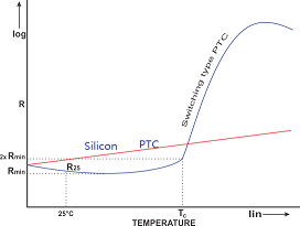
PTC thermistors RT Characteristics linear silicon vs switching ceramic
Positive Temperature Coefficient PTC thermistors fall into two major categories.
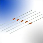
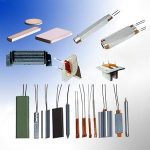
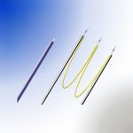
The first category consists of thermally sensitive silicon resistors, sometimes referred to as “silistors”. These devices exhibit a fairly uniform positive temperature coefficient (about +0.77%/C) through most of their operational range, but can also exhibit a negative temperature coefficient region at temperatures in excess of 150C. These devices are most often used for temperature measurement and temperature compensation.
Read more: ‘Linear Silicon PTC thermistors Temperature Sensor’
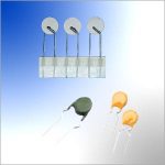
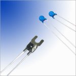
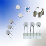
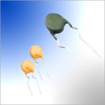
The other major category, and the one that we shall concentrate on in this section, are referred to as Switching PTC Thermistors. These devices are polycrystalline ceramic materials that are normally highly resistive but are made semiconductive by the addition of dopants. They are most often manufactured using compositions of barium, lead and strontium titanates with additives such as yttrium, manganese, tantalum and silica.
Switching PTC Thermistors have a resistance-temperature characteristic that exhibits a very small negative temperature coefficient until the device reaches a critical temperature, that is referred to as its “Curie”, switch or transition temperature. As this critical temperature is approached, the devices begin to exhibit a rising, positive temperature coefficient of resistance as well as a large increase in resistance. The resistance change can be as much as several orders of magnitude within a temperature span of a few degrees.
Thermistors Resistance vs. Temperature means the relation of zero-power resistance of PTC thermistor to PTC thermistor body temperature under a specified voltage. Zero-power resistance should be measured in super slot by using pulse power supply with low output impedance an stable output amplitude. Temperature rise of PTC thermistor induced by measuring current should be so limited that it could be ignored.
The resistance of the PTC thermistor is composed of the grain resistance and the grain boundary transition resistance. Particularly in the hot state, the strong potential barriers are determining resistance. Higher voltages applied to thePTC thermistor therefore drop primarily at the grain boundaries with the result that the high field strengths dominating here produce a break-up of the potential barriers and thus a lower resistance. The stronger the potential barriers are, the greater is the influence of this “varistor effect” on resistance. Below the reference temperature, where the junctions are not so marked, most of the applied voltage is absorbed by the grain resistance. Thus the field strength at the grain boundaries decreases and the varistor effect is quite weak.

PTC Thermistor RT Resistance vs. Temperature Characteristics
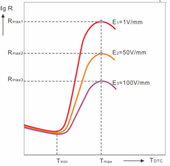
PTC Thermistor Resistance Temperature Curve Under Different Voltage
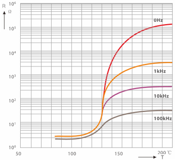
PTC Thermistor Resistance Temperature Curve Under Different Frequency
The properties of electrically loaded PTC thermistors (in self-heated mode) are better described by the I/V characteristic than by the R/T curve . It illustrates the relationship between voltage and current in a thermally steady state in still air at 25C, unless another temperature is specified.
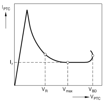
PTC Thermistor Voltage Current Characteristics
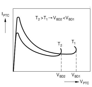
Influence of the ambient temperature on PTC Thermistor voltage current characteristics
The above Figure shows two I/V characteristics of one and the same PTC thermistor for two different ambient temperatures T1 and T2, with T1 < T2. At the higher temperature the PTC thermistor has a higher resistance value although the conditions are otherwise the same. Therefore, it carries less current. The curve for T2 is thus below that for T1. The breakdown voltage, too, depends on the ambient temperature. If the latter is higher, the PTC thermistor reaches the critical temperature where breakdown occurs on lower power or operating voltage. VBD2 is therefore lower than VBD1.
PTC Thermistor Current Time Characteristic Measure Circuit
PTC Thermistor Voltage Current Characteristic Measure Circuit
PTC thermistor Current vs Time Characteristic means current change characteristic vs. time. It is normally measured with memory oscilloscope by using measuring circuit as shown in the following.
Operating time of PTC thermistor decreases dramatically as initial current increases. Furthermore the operating time is in relation to resistance temperature coefficient, applied voltage and heat capacity of PTC thermistor. The following figure illustrate the PTC thermistor current time characteristics.
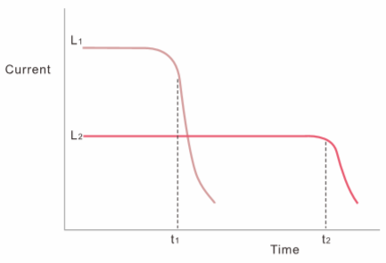
PTC Thermistor Current Time Characteristics
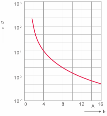
PTC Thermistor Operating Current vs. Operating Time
PTC Thermistor Zero Power R25 Resistance
DC resistance value of the PTC thermistor measured under 25C by adopting sufficiently low power consumption.
PTC Thermistor Temperature at Minimum Resistance
Temperature corresponding to minimum resistance.
PTC Thermistor Temperature Coefficient of Resistance
PTC thermistor temperature coefficient is calculated from the linear range at the steepest portion of resistance (Tb-Tp) . aT=(LnRp-LnRb) ·100/(Tp-Tb) (%/C)
Switch Temperature, Curie Temperature, Reference Temperature, Transition Temperature
The temperature at which the resistance value of the PTC thermistor increases to twice the zero-power resistance, also called PTC thermistor Curie temperature, or PTC thermistor Reference temperature, or PTC thermistor transition temperature.
PTC Thermistor Maximum Operating Voltage (Vmax)
The maximum rated voltage the PTC thermistor can continuously endure at 25C.
PTC Thermistor Maximum Inrush Current
The maximum current (effective value) through the PTC thermistor under max. rated voltage. Exceeding this current may result in damage to the PTC thermistor components.
Non-trip Current, Rated Current or Holding Current
Non-trip Current means the current at which PTC thermistor resistance does not exceed the specified value for designated time and temperature conditions, Also called PTC thermistor Rated Current or Holding Current, or Non-operating Current.
PTC Thermistor Trip Current, Operating Current
Initial current which causes PTC thermistor resistance to leap, also called PTC thermistor Operating Current.
PTC Thermistor Dissipation Factor
The ratio power dissipation change to temperature change of PTC thermistor (in mw/C). =P/(T-Tr)
P = dissipation power
T =thermistor body temperature
Tr =room temperature
PTC Thermistor Restore Time
Time for restore of PTC thermistor resistance to twice the zero-power resistance after power is switched off.
PTC Thermistor Temperature Range Under Maximum Voltage
Operating ambient temperature range that PTC thermistor can continuously operate under maximum voltage.
PTC Thermistor Breakdown Voltage
The maximum voltage that PTC thermistor can bear under stipulated time and temperature. PTC thermistor will breakdown exceeding this voltage.
PTC Thermistor Residual Current (Ir)
Current under heat balance state, after PTC thermistor resistance increases sharply, under maximum operating voltage.
PTC Thermistor Upper category temperature
Maximum ambient temperature that PTC thermistor can operate continuously.
PTC Thermistor Low Category Temperature
Minimum ambient temperature that that PTC thermistor can operate continuously.
Insulation Thermistor
Thermistor that satisfy stipulated insulation resistance and voltage test requirement.
Non-insulation thermistor
Thermistor that do not require insulation voltage and insulation resistance test.
PTC Thermistor Initial Current
The current that appears instantaneously in circuit switch starting to closing.
PTC Thermistor Peak Current
Peak-peak value of initial current.