How to Choose PTC Thermistors to Protect Telecom Equipment and Installations: Ceramic vs. Polymer?
Ceramic PTC Thermistors in Telecom Systems
To protect telecom installations against the effects of lightning, induced energies or the harmful direct contact between telecom and mains lines, protection components are used either directly on the line card or in the main distribution frame. Here Ceramic PTC thermistors have clear advantages in comparison to Polymer PTC thermistors. Considerations and selection criteria are presented in the following article.
Ceramic PTC thermistors have a unique feature: in a cold state they are low ohmic and when warmed, rapidly become high ohmic. In the cold state they are a good current conductor, having virtually no effect on the equipment to be protected. Self or foreign warming switches the PTC into a high impedance state thus reducing damaging over-currents to harmless levels.
Technology and Construction of Ceramic PTC Thermistors
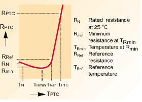
PTC Thermistor Typical Resistance Temperature Characteristics
A ceramic PTC thermistors is made of doped polycrystalline ceramic on a barium titanate substrate. In its pure form this material has high impedance. Semi-conduction and low resistance is achieved through doping with materials of a higher valence. Free ions form part of the crystal lattice which makes the ceramic conductive. The resistance of the PTC thermistor is composed of individual crystal and grain boundary resistances and can be represented by the formula R(PTC)= R grain + R grain boundary. The grain resistance is strongly temperature dependent. The operation of the PTC thermistor can best be described through (1) which displays the characteristics of an unloaded PTC , where the electrical load is kept as low as possible to limit change in the resistance through thermal accumulation.
Polymer PTC Thermistors
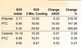
Ceramic Polymer PTC thermistors Resistance Change after condition
Other forms of PTC thermistors are available which are based upon a polymeric compound. These components comprise of a matrix of crystalline organic polymer containing conductive particles.
The sharp increase in the resistance characteristic results from the thermal expansion of the polymer.
In its cool state, the carbon particles have a close contact to each other.
In its warm state, the resistance increases due to the disconnection of the carbon.
The underlying principle of operation of a polymer PTC thermistor is thus physical movement as a result of heat.
The stability of the compound is subject to variation due to the physical change in the structure of the device. The stability of this process cannot be predicted or adequately controlled.
The data compares the ‘post trip’ characteristics of Ceramic and Polymer PTCs following an exposure to a 24-hour AC load and an additional cooling period of 3 minutes. The observed changes of the Polymer PTC is not acceptable for many telecom applications and many administrations specify a maximum difference in the TIP and RING resistances of 5%. Failure to comply with this condition can lead to echo or noise.
PTC Thermistors Responses Under Load
The ITU (International Telecommunication Union) have characterized disturbances that effect equipment and simulated these in two recommendations to test the resistibility of equipment to these disturbances. These recommendations are:
Recommendation K.20 – Resistibility of telecommunication equipment to over-voltages and over-currents and
Recommendation K.21- Resistibility of subscribers’ terminal to over-voltages and over- currents.
In both recommendations, the methods specified do not check the protective components themselves, but rather determine whether the equipment can withstand the testing and remain fully operational afterwards (Criteria A) or enter a fail-safe condition i.e. no risk of fire (Criteria B). However, as the suitability of components for line cards must be determined, manufacturers of switching equipment have now adopted some of these tests for their component approval specifications. For the Recommendation K.20 the following criteria are valid:
Lightning Simulation Tests: criteria A (3a)
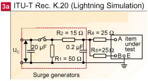
ITU-T K20 Lightning Simulation Test
When exposed to lightning simulation tests of short duration (1.0 kV, 10/700 us, Rs = 40 ohm), the PTC thermistor stays in its low resistance state since the pulse is too short to cause it to trip.
Power Induction Tests: criteria A (3b)
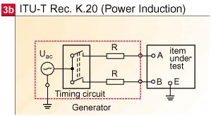
ITU-T K20 Power Induction Tests
Field trials on behalf of the ITU have shown that only equipment in exposed rural areas was damaged during thunderstorms days.
Line cards were damaged by induced currents of 4 – 6 A of 200 – 500 ms duration.
However such currents were seen as being rare and it was agreed that this test should simulate an over-current with a specific energy of 1 A 2s .
The 600 V(rms)/1A, test is intended to simulate an induced voltage from a neighbour power line and has a maximum duration of 0.2 seconds without primary protection and one second with this protection.
The PTC thermistor also stays low ohmic since the dissipation is too low to cause it to switch.
Power Contact: Criteria B (3c)
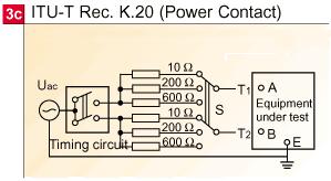
ITU-T K20 Power Contact Test
The direct contact of the telephone line to power line is potentially more damaging than lightning or power induction since the disturbance can last from minutes through to several days if undetected.
The susceptibility of the equipment is checked through the application of AC currents of differing amplitude for 15 minutes.
These currents pass through the PTC thermistor causing it to heat up. When its reference temperature (T REF) is exceeded, it dramatically increases its resistance thus restricting the flow of this harmful current into the equipment.
Under these conditions with a 10 ohm PTC thermistor typical switching speeds between 0.1 to 19 s could be expected as shown in the following.
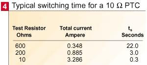
Typical Switching Time for 10 ohm PTC thermistor
PTC Thermistors Selection Criteria
Due to their excellent protection properties ceramic PTC thermistors are increasingly being used in new Line Cards. To offer protection to older generation line cards, there is an increasing trend to use PTCs in the Main Distribution Frame. The requirement for matching (both pre- and post-time) with fast cooling characteristics applies to both areas of application.
A prolonged contact with a 230 V power line can go undetected for many hours, meaning that the PTC thermistor must stay in the high impedance condition without disturbing its functionality. This condition is recognized by CECC 44001 where Overload PTC thermistors must withstand the Rated Voltage in the Tripped Condition for 1000 hours with a maximum variation of 10 %.
Most Ceramic Telecom PTCs have a rated voltage of 230 V and thus will comply to this condition.
Most Polymer PTC thermistors have a maximum rated voltage <60V and hence are not suitable for telecom applications with exposure to mains voltages.
Usually two PTC thermistors are required, one for the TIP circuit and one for the RING. The maximum imbalance between the two PTC thermistors resistances must be defined not only for the pre-trip but more importantly, following a short cooling period, for the post-trip. This is to ensure the quality of the transmission following a disturbance. Telecom PTC thermistors are delivered in classes (matched versions), this difference should also apply after the 3-minute cooling period post-trip.
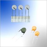
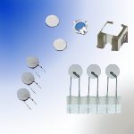
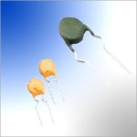
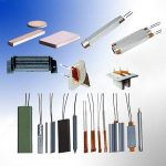
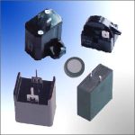
Forms of PTC thermistors
Irrespective of their form, the basic construction of Ceramic PTC thermistors is the same: a ceramic compound pressed into a disc with metallization layers on both sides for the electrical terminations.
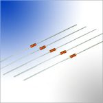
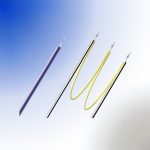
Radial Leaded Disc PTC thermistors
Still the most popular form of PTC is the leaded disc. Here the electrical connections are made through leads with a pitch of 5mm. These are available in bulk or taped. Field of application is both line card and MDF.
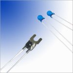
Pill PTC thermistors
PTC thermistors pills are delivered with two forms of terminals; for soldering or for clamping through spring loaded contacts. The latter will however lead to a change in the electrical characteristics of the PTC thermistor as the contacts will dissipate heat away from the PTCchanging its switching behavior for a given current. It is therefore essential that the desired performance is discussed in detail since appropriate tests must be undertaken. Field of application is mainly MDF but can also be used on line card hybrids as mentioned above.