Ceramic PTC Thermistor for Telecom High Voltage Current Surge Protection
PTC Thermistors Telecom Protect
Ceramic positive temperature coefficient PTC thermistor help provide protection against power cross, power induction surges and lighting surge defined in ITU, Telcordia, UL.
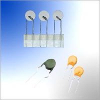
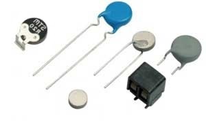
Available in chip, radial-leaded coated and non-coated configuration.
This thermally sensitive semiconductor resistor provides reversible, self-resetting fuse protection against over-currents short circuit for telecommunication line protector units, improve the reliability of custom premises and network equipment.
PTC Thermistor Current Limiting Protection Device can be found providing resettable line protection at the exchange, monitoring hot spots and protecting ringers, battery feeds, transformers, switches and relay circuits. Also used extensively to protect the mobile phone’s battery pack against overcharging in land-based and radio mobile communications.
This page is focus on PTC thermistor for ITU-T K20 K21 K45 standard requested high volage current surge protection.
Advanced developments in telecom equipment in recent years have radically altered the protection requirements of both exchange and subscriber equipment. PTC Thermistor Current Protector must protect the telephone line circuit against overcurrent, which may be caused by the following examples:
- Surges due to lighting strikes on or near to the line plant.
- Short-term induction of alternating voltage from adjacent power lines or railway systems, usually caused when these lines or systems develop faults.
- Direct contact between telephone lines and power lines.
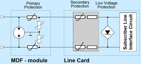
To provide good protection under such conditions, a PTC thermistor is connected in series with each line, usually as secondary protection; However, even with primary line protection (usually a gas discharge tube), the PTC thermistor must fulfill severe requirements.
Surge pulses of upto 2KV can occur and in order to withstand short term power induction, the PTC thermistor must withstand high voltages.
If the line has primary protection, a 220V to 300V PTC thermistor is adequate.
Without primary protection, 600V PTC device is necessary.
We can manufacture a series of PTC thermistor fulfilling both requirements.

PTC thermistor Replacement Benefits
- Automatic reset from protective trip up to 265V AC line contact
- Compatible with the 600V over voltage test by UL60950
- High resistance to the lighting surge (A surge absorber is still required to protect SLIC)
- Central Office Switching Equipment (C.O): analog and digital line cards, POTS, T1/E1 equipment, xDSL modems and splitters, multiplexers, CSU/DSU, servers.
- Primary Protection Modules: MDF (main distribution frame) modules, network interface devices (NIC).
- Custom Premises Equipment, also known as subscriber terminal equipment (T.E.), IT equipment: Modem, phone sets, fax machines, phone wall outlet (plugs), alarm systems, answering machine, PBX systems, ADSL Splitters, internet appliance, POS terminals.
- Access Network hardware, LAN WAN equipment, Powered Ethernet systems, VoIP (voice over IP equipment), integrated voice data (IVD), Set-top box (S.B), etc.
- Landline telephones or FAX machines
- Telephone interface of STB, VoIP equipment
- Any other equipment of communication facility having a phone line interface
- Compliant with ITU-T K20 K21 K45
–Basic level lightning surges (10/700μs)
–Basic level power Induction (600V,1A,0.2S)
–Power contact criteria A/B (230V,15min.) - Suitable for continuous connection to main voltage 110/230 VAC in tripped (high ohmic) condition.
- Round leadless disk thermistor available for combined usage of PTC and primary protection, e.g gas arrestor.
- Thermistor disk coated non-coated construction, diameter 5mm to 10mm.
- Typical Resistance @25C (R25) 10 ohm, 12 ohm, 18 ohm, 20 ohm, 25 ohm, 50 ohm, 55 ohm.
- Matching available with narrow resistance tolerance.
- Tight resistance tolerance maintained after switching.
- Negligible resistance drift after soldering or switching.
Rated Zero-power Resistance (R25)
Operating temperature range: 25±2℃, Within the allowable tolerance.
Non-operating Characteristic
Operating temperature range: 40±2℃.
In static air for 30min.
Max. voltage: 60VDC.
Non-operating current.
Energized time: 60min.
(R-R25)/R25≤50%
Over-current operating characteristic
Operating temperature range: 25±2℃,
Max. voltage of power supply: 220Vrms.
Test the time for the current decrease to limited value. See the spec. Table.
Over voltage withstanding (Power line contact)
Voltage of power supply: 250VAC,
Initial current: 3A,
Energized time: 30min .
Restore time in room temperature 4 hours,
then test the R25. ΔR/R25≤20%.
Over current withstanding
Max. voltage of supply: 220VAC,
Initial current: 3A.
ON 60S, OFF 600S ,
Cycle:30 times,
Restore time in room temperature is 4 hours,
then re-test the Rn. ΔR/Rn≤20%.
Surge current withstanding
Current waves: 10/1000μS,
Minimum opening circuit voltage: 1.0kv,
Peak current: 25A,
Interval: 3min,
Cycle:30 times,
Restore time in room temperature is 4 hours,
then re-test the R25. ΔR/R25≤20%.
Induction voltage current withstanding (Only for maximum voltage more than 600V)
Max. voltage of supply: 650VAC,
Initial current: 1.1A,
ON 60S, OFF 600S,
Cycle:10 times,
Restore time in room temperature 4 hours,
then re-test the R25. ΔR/R25≤20%.
Fail Model
I. Voltage of power supply: 250VAC. Initial current: 10Arms,
II. Voltage of power supply: 600VAC. Initial current: 15Arms.
III. Voltage of power supply: 650VAC. Initial current: 10Arms.
Energized time: 30min.
High resistance or open circuit is allowable. Low resistance state or firing is not allowed.
Restore time
The necessary time of a PTC to return to twice of R25. ≤60S.

| AMWEI Part Number | Resistance @25C R25 (Ohm) |
Non-trip current Int (mA) |
Trip current @25C It (mA) |
Tripping time @ max current (Seconds) |
Max. current Imax (A) |
Max. voltage Vmax (V) |
Fail model | Dimension (mm) |
|||
|---|---|---|---|---|---|---|---|---|---|---|---|
| @25C | @40C | Dmax | Tmax | Φd | |||||||
| AMZ23-10RM130 | 10 ohm | 130mA | 100mA | 260mA | <0.2s | 2.0A | 250V | 250V/10A | 7.5 | 4.0 | 0.6 |
| AMZ23-10RM150 | 10 ohm | 150mA | 100mA | 260mA | <0.3s | 2.0A | 250V | 250V/10A | 9.0 | 5.0 | 0.6 |
| AMZ23-12RM130 | 12 ohm | 130mA | 100mA | 260mA | <0.3s | 2.0A | 250V | 250V/10A | 9.0 | 5.0 | 0.6 |
| AMZ23-12RM090 | 12 ohm | 90mA | 60mA | 160mA | <0.2s | 2.0A | 250V | 250V/10A | 9.0 | 5.0 | 0.6 |
| AMZ23-20RM100 | 20 ohm | 100mA | 80mA | 200mA | <0.2s | 3.0A | 250V | 250V/10A | 9.0 | 4.0 | 0.6 |
| AMZ23-35RM090 | 35 ohm | 90mA | 75mA | 180mA | <0.2s | 3.0A | 250V | 250V/5A | 9.0 | 5.0 | 0.6 |
| AMZ23-40RM080 | 40 ohm | 80mA | 70mA | 160mA | <0.2s | 3.0A | 250V | 250V/5A | 9.0 | 5.0 | 0.6 |
| AMZ23-50RM070 | 50 ohm | 70mA | 60mA | 150mA | <0.2s | 3.0A | 250V | 250V/5A | 9.5 | 5.0 | 0.6 |
| AMZ23-50RM075 | 50 ohm | 75mA | 60mA | 150mA | <0.2s | 3.0A | 650V | 650V/10A | 9.5 | 5.0 | 0.6 |
| AMZ23-55RM070 | 55 ohm | 70mA | 60mA | 150mA | <0.2s | 3.0A | 650V | 650V/10A | 9.5 | 5.0 | 0.6 |
| AMZ25-9RM160 | 9 ohm | 160mA | 130mA | 330mA | <0.8s | 3.0A | 250V | 250V/10A | 10.5 | 4.5 | 0.6 |
| AMZ25-25RM100 | 25 ohm | 100mA | 80mA | 220mA | <0.2s | 3.0A | 250V | 250V/10A | 6.6 | 4.0 | 0.6 |
| AMZ25-25RM120 | 25 ohm | 120mA | 100mA | 300mA | <0.4s | 3.0A | 250V | 250V/10A | 8.2 | 4.0 | 0.6 |
| AMZ26-35RM080SMD | 35 ohm | 80mA | 60mA | 180mA | <0.2s | 2.5A | 250V | 250V/10A | / | / | / |
Note: Standard Resistance @25C (R25) allowable tolerance +/-20%, if not specified.
| AMWEI Part Number | Resistance @25C R25 (Ohm) |
Non-trip current Int (mA) |
Trip current @25C It (mA) |
Tripping time @ max current (Seconds) |
Max. current Imax (A) |
Max. voltage Vmax (V) |
Dimension (mm) |
|||
|---|---|---|---|---|---|---|---|---|---|---|
| @25C | @40C | Dmax | Tmax | Φd | ||||||
| AMZ21-10RM150 | 10 ohm | 150mA | 130mA | 350mA | <4.0s | 3A | 230V | 7.2 | 1.5 | / |
| AMZ21-18RM110 | 18 ohm | 110mA | 90mA | 220mA | <0.15s | 3A | 250V | 5.5 | 1.5 | / |
| AMZ21-18RM125 | 18 ohm | 125mA | 110mA | 250mA | <0.18s | 3A | 250V | 5.5 | 2.0 | / |
| AMZ21-18RM130 | 18 ohm | 130mA | 110mA | 260mA | <0.18s | 3A | 250V | 6.2 | 2.0 | / |
| AMZ21-18RM135 | 18 ohm | 135mA | 110mA | 270mA | <0.2s | 3A | 250V | 6.6 | 2.0 | / |
| AMZ21-20RM085 | 20 ohm | 85mA | 70mA | 170mA | <0.18s | 3A | 250V | 6.2 | 2.0 | / |
| AMZ21-25RM055 | 25 ohm | 55mA | 45mA | 110mA | <0.4s | 2A | 230V | 5.3 | 2.0 | / |
| AMZ21-25RM060 | 25 ohm | 60mA | 50mA | 120mA | <0.4s | 2A | 230V | 5.3 | 2.0 | / |
| AMZ21-25RM085 | 25 ohm | 85mA | 75mA | 170mA | <0.7s | 2A | 230V | 5.3 | 2.0 | / |
| AMZ25-25RM055 | 25 ohm | 55mA | 45mA | 110mA | <0.4s | 1A | 230V | 5.3 | 4.0 | 0.6 |
| AMZ25-25RM060 | 25 ohm | 60mA | 50mA | 120mA | <0.4s | 1A | 230V | 5.3 | 4.0 | 0.6 |
| AMZ25-20RM145 | 20 ohm | 145mA | 100mA | 250mA | <0.2s | 3A | 250V | 6.6 | 4.0 | 0.6 |
| AMZ25-10RM130 | 10 ohm | 130mA | 110mA | 260mA | <4.0s | 1A | 230V | 6.6 | 4.0 | 0.6 |
| AMZ25-10RM150 | 10 ohm | 150mA | 135mA | 300mA | <7.0s | 1A | 230V | 8.2 | 4.0 | 0.6 |
| AMZ25-18RM125 | 18 ohm | 125mA | 110mA | 250mA | <1.0s | 1A | 230V | 5.5 | 4.0 | 0.6 |
| AMZ23-18RM135 | 18 ohm | 135mA | 110mA | 270mA | <0.2s | 3A | 250V | 7.5 | 4.5 | 0.6 |
| AMZ23-18RM110 | 18 ohm | 110mA | 90mA | 220mA | <0.2s | 3A | 250V | 9.0 | 4.5 | 0.6 |
| AMZ23-20RM100 | 20 ohm | 100mA | 80mA | 200mA | <0.2s | 3A | 250V | 9.0 | 4.5 | 0.6 |
| AMZ23-25RM085 | 25 ohm | 85mA | 75mA | 170mA | <0.7s | 1A | 230V | 6.5 | 5.0 | 0.6 |
| AMZ23-25RM090 | 25 ohm | 90mA | 70mA | 180mA | <0.2s | 3A | 250V | 9.0 | 4.5 | 0.6 |
Note: Standard Resistance @25C (R25) allowable tolerance +/-20%, if not specified.
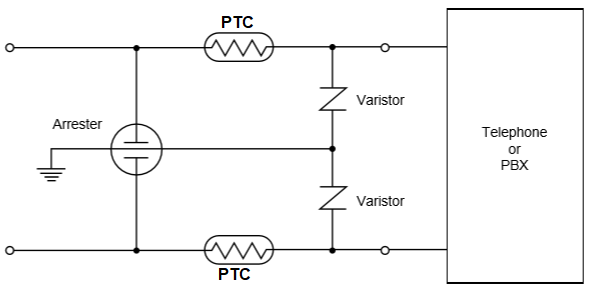
An example of PTC Thermistor for telecom circuit protection
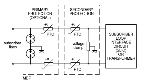
Telephone line PTC thermistors used for overcurrent protection
PTC Thermistor Telecom Application
Rated current and temperature
The PTC thermistor is primarily used to protect the switching equipment against fault current through direct contact with a power line (power contact) or an induced surge of short duration and low voltage from a neighboring line (power induction).
For obvious reasons, the rated current of the PTC thermistor should be kept as low as possible so that the protection responds quickly to overcurrents. The rated current should typically be slightly higher than the operating current of the system to be protected at the normal operating temperature.
Here the dependence of the rated current on the temperature of the ambient must be considered.
Duration of disturbance — voltage classes
An aspect that is too often neglected is the duration of the power contact. Such disturbances can go undetected for many hours, meaning that the PTC thermistor could be held in the high resistance condition exposed to the line voltage for an indefinite period.
AMWEI PTC thermistors for telecommunication applications have a maximum switching voltage of at least 265 V AC and can withstand this condition indefinitely.
Imbalance on the line — resistance of PTC thermistor
For most telecom applications the balance between the tip and ring (often referred to as longitudinal balance) is essential. A figure must be assigned to the balance between the line resistances that must apply initially and, after a short cooling period, after operation.
Typically 1 Ω is demanded on delivery, which should also apply throughout the service life of a system.
As opposed to PTC thermistor made of plastic materials, ceramic PTC thermistor always return to their initial resistance value, even after frequent heating/cooling cycles.