PTC Thermistor Motor Starter
PTC Thermistor Motor Starter
PTC Thermistor Motor Starter is PTC Thermistor used for delaying the switch-off of the motor starter auxiliary winding (after the motor has accelerated) to protect the winding from damage.
PTC Thermistor Motor Starter packages can be economical solid state torque assist for heat pumps, room air, commercial and residential air conditioning and refrigeration systems. PTC thermistor can be used to protect the auxiliary starter winding of induction motors or single phase motors.
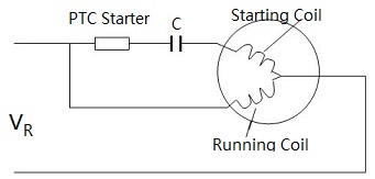
When the circuit is turned on, the PTC has a low resistance and most of the line voltage is applied to the starter winding. After motor starting, the PTC heats up and switches to a high resistance state. The time for this to occur is determined by the size and resistance of the PTC, as well as the amount of current flowing through the starter winding.
When the PTC has reached a high resistance state, the current flowing through it, as well as the starter winding, falls substantially. Once the motor winding temperature reaches the trip temperature of the PTC thermistor, its resistance increases several orders of magnitude for a small increase in temperature.
Compared to the alternative start capacitor and relay, PTCR Motor start devices save several wires, occupy less panel space, mount more easily, and cost less.
Single-phase motor start assist in refrigerator systems, air-conditioning systems, heat-pumps, small compressors.
Inrush current generation.
- Complete range of size resistance combination for 120V, 240V compressor motors.
- Rugged silver electrodes well suited for long life pressure contact mounting.
- Various pellet sizes for optimum inrush current and switching time.
- Typical resistance @25C 4.7 ohm, 6.8 ohm,15 ohm, 22 ohm, 33 ohm.
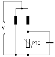
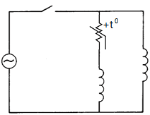
Simple PTC thermistor starter circuit diagram for single-phase AC motors
Single phase induction motors (e.g in compressors for refrigerators and air conditioners) can effectively be started when an auxiliary coil is used in the starting phase. The auxiliary coil is cut off from the circuit after the starting phase. For this purpose, PTC thermistor is employed.
When high voltage is applied to the PTC thermistor, the high current causes PTC thermistor to heat up and eventually the resistance to increase. A high current flows initially (starting phase ) and then decreases in relation to the increase in resistance. After the starting phase, a low residual current flows the auxiliary coil.
The PTC thermistor is used for delaying the switch-off of the starter auxiliary winding (after the motor has accelerated) to protect the winding from damage.
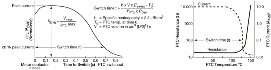
PTC Current vs. Time Showing Definition Rdyn and Switch Time Graph
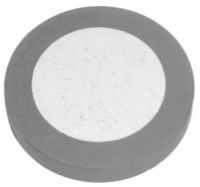
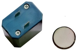
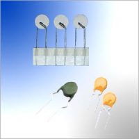
PTC Thermistor Motor Starter Pellet
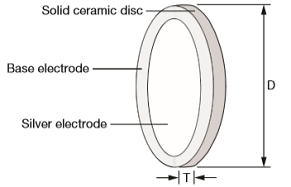
PTC Motor Starter Pellet Construction
| Resistance @25C R25 (ohm) |
Max. Voltage (V) |
Max. Current (A) |
Starting Time (Seconds) |
Power Consumption (W) |
Recovery Time (Seconds) |
Coil Resistance (ohm) |
Switching Temperature Centigrade |
Diameter (mm) |
Thickness (mm) |
|---|---|---|---|---|---|---|---|---|---|
| 4.7 ohm | 180V | 12A | 0.5-2.5S | 3.5W | 100S | 10 ohm |
120C |
19.5 +/-1.0 mm |
2.5 +/-0.2 mm |
| 6.8 ohm | 200V | 10A | 0.2-1.5S | 3.5W | 100S | 25 ohm | |||
| 15 ohm | 350V | 8A | 0.2-1.5S | 3.0W | 100S | 30 ohm | |||
| 22 ohm | 350V | 7A | 0.2-1.5S | 3.0W | 85S | 30 ohm | |||
| 33 ohm | 350V | 6A | 0.2-1.5S | 3.0W | 85S | 55 ohm | |||
| 47 ohm | 400V | 5A | 0.2-1.5S | 3.0W | 75S | 55 ohm | |||
| 4.7 ohm | 180V | 12A | 0.2-1.3S | 3.3W | 85S | 10 ohm |
120C |
16 +/-0.5 mm |
2.5 +/-0.2 mm |
| 6.8 ohm | 180V | 10A | 0.2-1.2S | 3.3W | 90S | 10 ohm | |||
| 15 ohm | 350V | 8A | 0.2-1.2S | 2.8W | 100S | 30 ohm | |||
| 22 ohm | 350V | 7A | 0.2-1.0S | 2.8W | 85S | 30 ohm | |||
| 33 ohm | 350V | 6A | 0.2-1.0S | 2.8W | 85S | 30 ohm | |||
| 47 ohm | 350V | 5A | 0.2-1.0S | 2.8W | 80S | 30 ohm |
| Test Item | Standard | Test conditions | ΔR25/R25 |
|---|---|---|---|
| Switching test at room temperature | IEC60738-1 | Imax Vmax Number of cycles: 10000 cycles | <25% |
| Rapid change of temperature in air | IEC600628-2-14, Test Na | T=TLCT, T=TUCT Number of cycles: 5 cycles T:30min | <20% |
| Endurance at max. operating temperature and max. operating voltage | IEC60738-1 | Ambient temperature: +60C Maximum Operating Voltage Current limited to Imax. Time: 24 hours | <25% |
| Storage in damp heat | IEC 600628-2-3 | Temperature of air: 40C Relative humidity of air: 93% Duration: 56 days | <20% |
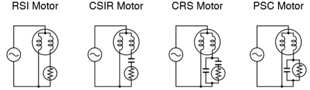
PTC thermistor motor starter for RSI CSIR CRS PSC motors
Motor Starting Circuit Diagram
Starting Circuit Diagram with PTC Thermistor Motor Starter
Other AMWEI PTC Thermistors Products for Motor Application

Content Headline
What Is PTC Thermistor Motor Starter?
PTC Thermistor Motor Starter Application
How PTC Thermistor Motor Starter Work? Operating-Principles
Thermistors Application


PTC Thermistor Tech
PTC Thermistor Tech
PTC thermistors Glossary and Definition
3 PTC thermistors characteristics, Resistance vs. Temperature RT Characteristic, Voltage vs. Current VI characteristic, Current vs Time Characteristic.
PTC thermistors Application Cautions for Soldering, Mounting, Cleaning.
PTC thermistors Manufacturing and Quality Control.